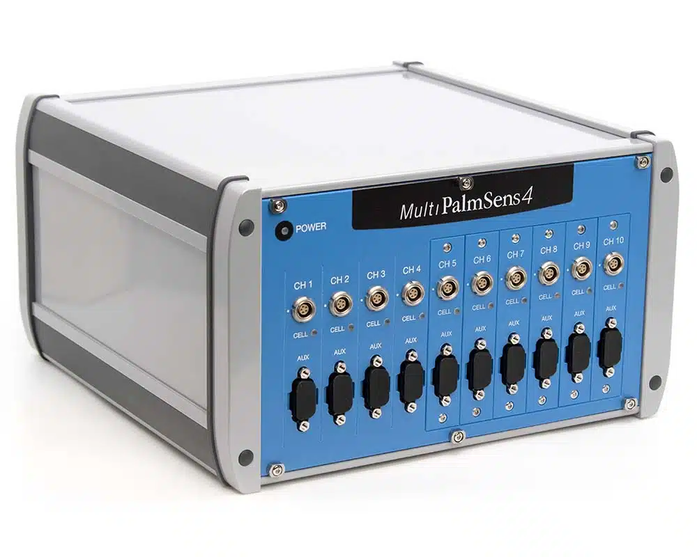
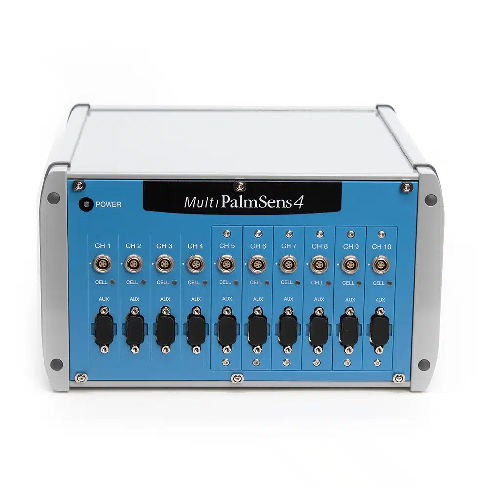
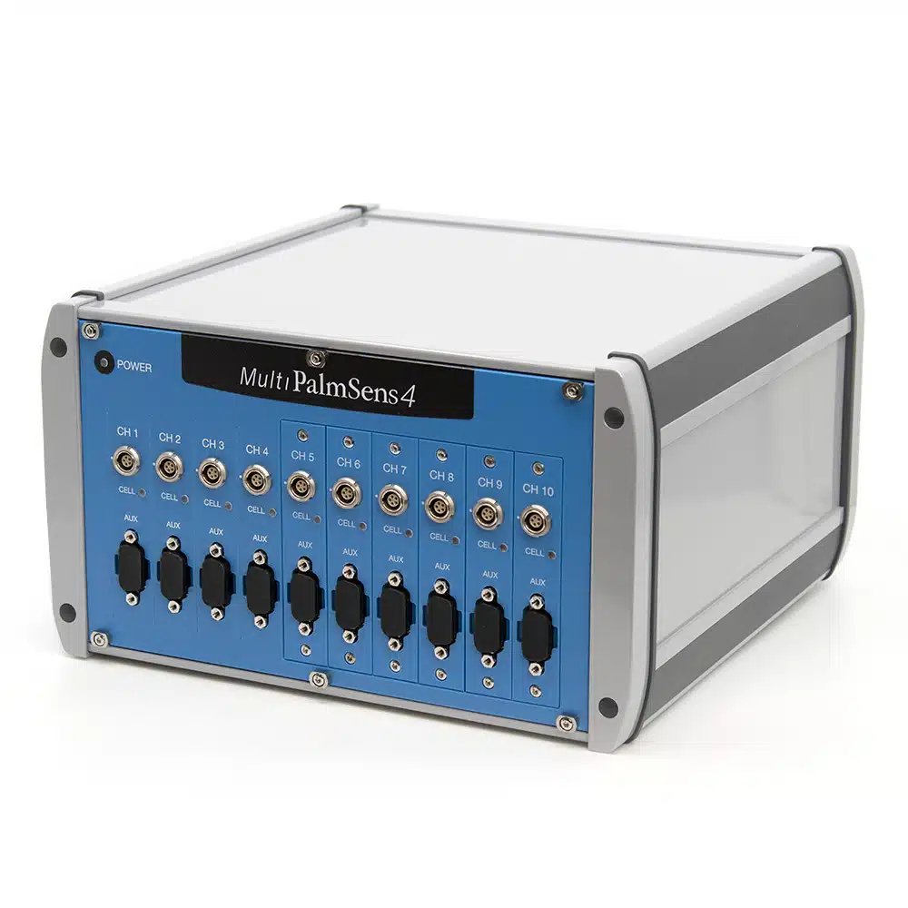
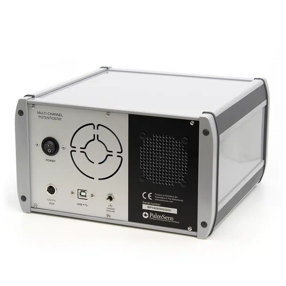
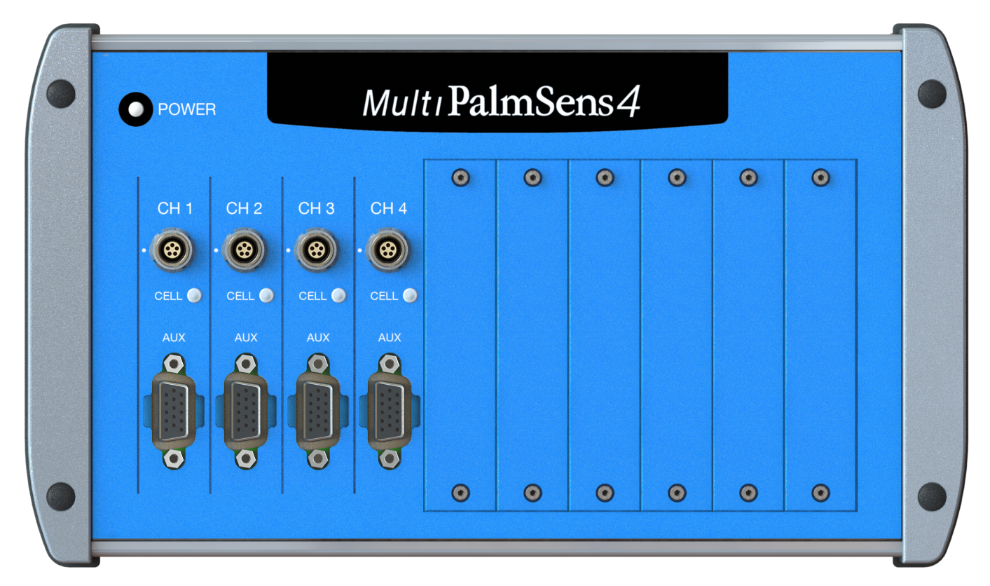
MultiPalmSens4
Multi-channel Potentiostat / Galvanostat / Impedance Analyzer
- 4 to 10 channels available in different configurations
- FRA / EIS: 10 μHz up to 1 MHz
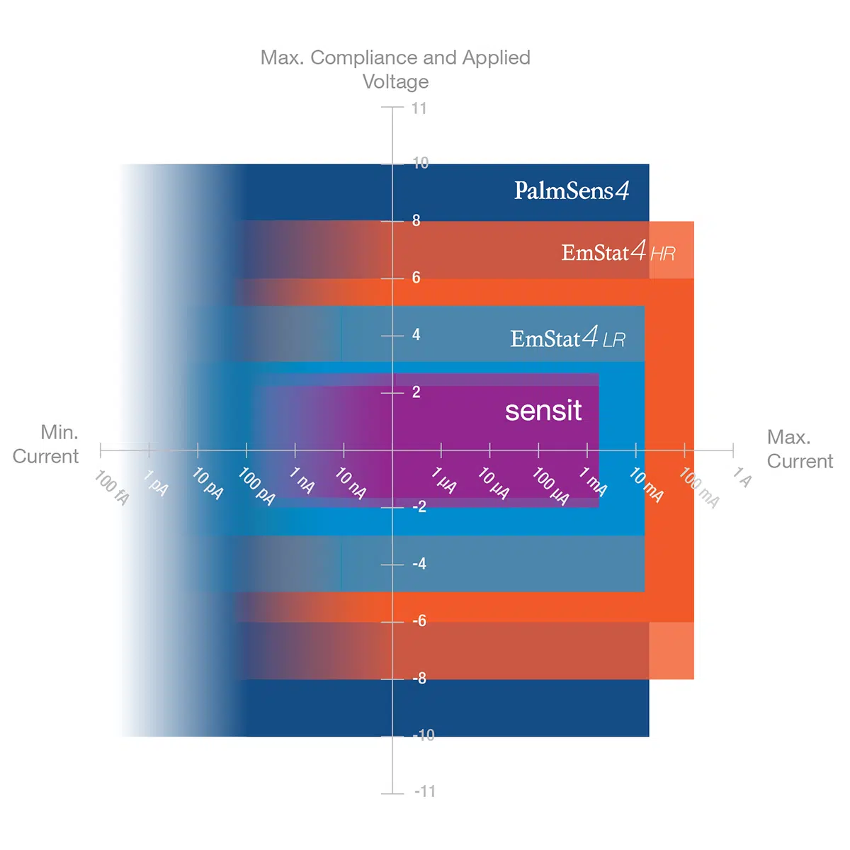
- 9 current ranges: 100 pA to 10 mA
- potential range: ±5 V or ±10 V
Description
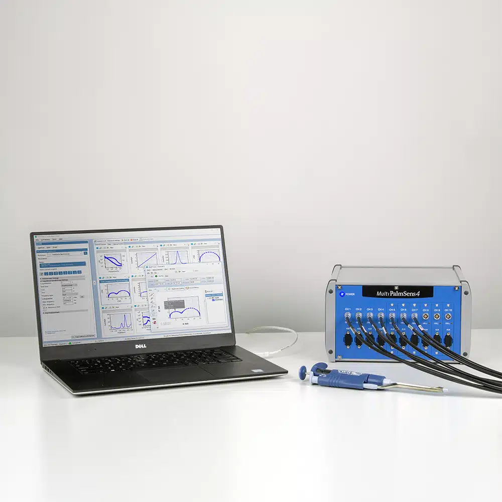
The MultiPalmSens4 is a flexible multi-channel potentiostat, galvanostat and impedance analyzer which you can fully tailor to your requirements and budget. The MultiTrace software allows for using each channel individually or simultaneously or running a sequence of automated tasks on each channel. Each channel provides an additional auxiliary port for controlling peripherals or monitoring temperature or other analog signals.
Configure your ideal multi-channel potentiostat
Each channel can be configured with:
- ±5 V or ±10 V maximum potential range
- EIS/FRA with maximum frequency of 100 kHz or 1 MHz
- Bipotentiostat module for second WE
- iR-Compensation
- Galvanic isolation
Always a backup
Every channel of the MultiPalmSens4 is equipped with 8 GB storage space. This means all your measurements* can automatically be saved on-board as backup.Measurements can be browsed and transferred to the PC easily using the MultiTrace software for Windows.
Synchronizing channels in Synched mode
By enabling synchronization of channels and adjusting the setup of your cables, you can use the MultiPalmSens4 as a polypotentiostat. This means you can use multiple working electrodes, one counter and one reference electrode in the same cell at the same time. Your working electrodes all perform the same measurement.
Specifications
For each channel:
| General | ||
|---|---|---|
| configuration | PS4.F#.05 | PS4.F#.10 |
dc-potential range
The maximum potential difference, that can be applied between WE and RE.
|
±5 V | ±10 V |
compliance voltage
The compliance voltage is the maximum voltage that can be applied between the working and counter electrode. Another name could be the maximum cell potential. Continue reading
|
±10 V | |
| maximum current | ±30 mA (typical) | |
| max. acquisition rate | 150,000 data points/s | |
| Potentiostat (controlled potential mode) | |
|---|---|
applied dc-potential resolution
The lowest observable difference between two values that a measurement device can differentiate between.
|
76.3 µV |
applied potential accuracy
The applied potential accuracy describes how close to the real values your applied potential is.
|
≤ 0.1% ±1 mV offset |
current ranges
A potentiostat measures current. For optimal precision, the range between which currents are measured is split into multiple current ranges. A current range defines the maximum current a potentiostat can measure in a certain range. This means it will also determine the resolution, because the number of bits or rather states is fixed, while the current range is variable.
|
100 pA to 10 mA (9 ranges) |
current accuracy
The current accuracy describes how close to the real values your measured current is.
|
< 0.2% of current ±10 pA ±0.1% of range |
measured current resolution
The lowest observable difference between two values that a measurement device can differentiate between.
|
0.005 % of current range ( 0.0025% of 10 mA range |
| Galvanostat (controlled current mode) | |
|---|---|
current ranges
A potentiostat measures current. For optimal precision, the range between which currents are measured is split into multiple current ranges. A current range defines the maximum current a potentiostat can measure in a certain range. This means it will also determine the resolution, because the number of bits or rather states is fixed, while the current range is variable.
|
1 nA to 10 mA (8 ranges) |
| applied dc-current | ±6 times applied current range |
| applied dc-current resolution | 0.0076% of applied current range (<10 mA) 0.0038% of 10 mA range |
| applied dc- current accuracy
The current accuracy describes how close to the real values your measured current is.
|
< 0.2% of current ±10 pA ±0.1% of range |
| potential ranges | 10 mV, 100 mV, 1 V |
| measured dc-potential resolution | 78.13 μV at ±10 V 7.813 μV at ±1 V 0.7813 μV at ±0.1 V |
| measured dc-potential accuracy | ≤ 0.05% or ±1 mV (for |E| < ±9 V) ≤ 0.2% (for |E| ≥ ±9 V) |
| FRA / EIS (impedance measurements) | ||
|---|---|---|
| Configuration | PS4.F1.## | PS4.F2.## |
| frequency range | 10 μHz to 100 kHz | 10 μHz to 1 MHz |
| ac-amplitude range | 1 mV to 0.25 V rms, or 0.7 V p-p | |
| GEIS (galvanostatic impedance measurements) | |
|---|---|
| frequency range | 10 μHz to 100 kHz |
| ac-amplitude range | 0.001 x CR to 0.4 x CR (<10 mA) 0.001 x CR to 0.2 x CR (10 mA) (CR = current range) |
| Electrometer | |
|---|---|
electrometer amplifier input
The amplifier input resistance of the amplifier in the electrometer determines the load that the amplifier places on the source of the signal being fed into it. Ideally the resistance is infinite, and the load to be zero to not to influence your measurement.
|
> 1 TΩ // 10 pF |
| bandwidth | 1 MHz |
| Other | |
|---|---|
| housing | 15 x 25 x 25 cm |
| weight | +/- 4 kg |
| temperature range | 0 ºC to + 50 ºC |
| power supply | External 12V AC/DC adapter |
| communication | USB |
| internal storage space | 8 GB per channel or +/- 800000 measurements incl. method info (assuming 200 data points per measurement) |
| Auxiliary port (D-Sub 15) | |
|---|---|
| analog input | ±10 V, 18 bit |
| analog output | 0-10 V, 12 bit (1 kOhm output impedance) |
| 4 digital outputs | 0-5 V |
| 1 digital input | 0-5 V |
| i-out and E-out | raw output of current and potential E-out ±10 V (1 kOhm output impedance) i-out ±6 V (1 kOhm output impedance) |
| power | 5 V output (max. 150 mA) |
| EIS Accuracy Contour Plot |
|---|
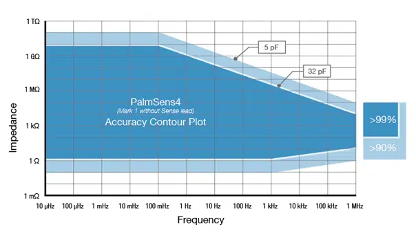 |
Electrochemical Impedance Spectroscopy (EIS) is an electrochemical techniques to measure the impedance of a system in dependence of the AC potentials frequency. With this option you can select the maximum AC frequency for EIS.
BiPot stands for BiPotentiostat, which is a potentiostat with two working electrodes. A bipotentiostat can use two working electrodes, one reference and one counter in the same cell. The two working electrodes can be operated and monitored exactly at the same time. Working electrode 1 performs any of the supported techniques (see below), while working electrode 2 can either have its own constant potential or follow the working electrode 1’s potential. In the latter case a potential offset can be added.
The resistance between the reference electrode and the double layer of the specimen can cause a significant potential drop, decreasing the applied potential where it is required. The module provides positive feedback to compensate for the IR drop between the Reference electrode and the outside of the double layer of the electrochemical cell.
Accessories
Main extensions for MultiPalmSens4
You may also like…
Software
MultiTrace for Windows
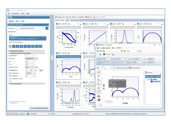
The MultiPalmSens4 comes with MultiTrace for Windows. MultiTrace allows the instrument to be controlled in two different modes: Individual and Simultaneous channel control mode.
Individual mode
The individual mode gives an overview of all channels. Each channel can be selected separately and can run a measurement independently in parallel with other channels. You can also run a script for a sequence of measurements and other actions on each channel.
Simultaneous mode
In the Simultaneous Mode the MultiPalmSens4 works with all channels running the same measurement in parallel at the same time. There is only one active method in the Method Editor which is started on all selected channels simultaneously upon start. All results are presented as overlays in the same plot.
Software Development Kits
PalmSens provides several Software Development Kits (SDKs) to help developers create custom software to control their potentiostat. Each SDK comes with documentation and examples that shows how to use the libraries.
SDKs are available for:
- .NET (WinForms, WPF and Xamarin for Android)
- Python
- LabVIEW
- Matlab

Downloads
Documentation (1)
| Name | Last updated | |
|---|---|---|
| MultiPalmSens4 Brochure A detailed description of the MultiPalmSens4 multi-channel potentiostat. | 22-01-25 |
Application Note (4)
| Name | Last updated | |
|---|---|---|
| Multichannel, polypotentiostat or multiplexer This will help you to choose the ideal multi-channel instrument for your application. | 22-01-25 | |
| Multi-Channel: Multiple Working Electrodes in the Same Cell Learn how to use a multi-channel potentiostat as a polypotentiostat, so you can use multiple working electrodes in the same cell sharing one reference and counter electrode. | 19-01-22 | |
| Potentiostatic and Galvanostatic EIS What is GEIS? When to use GEIS or PEIS? | 14-12-20 | |
| Galvanic Isolation In this application note the galvanic isolation options are discussed for the different PalmSens instruments as well as the effect of galvanic isolation on your measurement. | 08-04-20 |
Software (1)
| Name | Last updated | |
|---|---|---|
| MultiTrace – PC Software for all Multi-channel instruments The MultiTrace software controls the individual channels of our multi-channel instruments. You can also combine multiple single-channel instruments. | 17-03-22 |


